显示标签为“BMW Icom a2 bc”的博文。显示所有博文

2017年12月9日星期六

BMW ICOM A2+B+C WIFI Setting Guide

Here is a tutorial on how to set WIFI for BMW ICOM A2+B+C diagnostic & programming tool, hope it helps.
STEP1:make sure you ICOM A2 have a WIFI card
go to 169.254.92.38/60080
user:root
pass: NZY11502
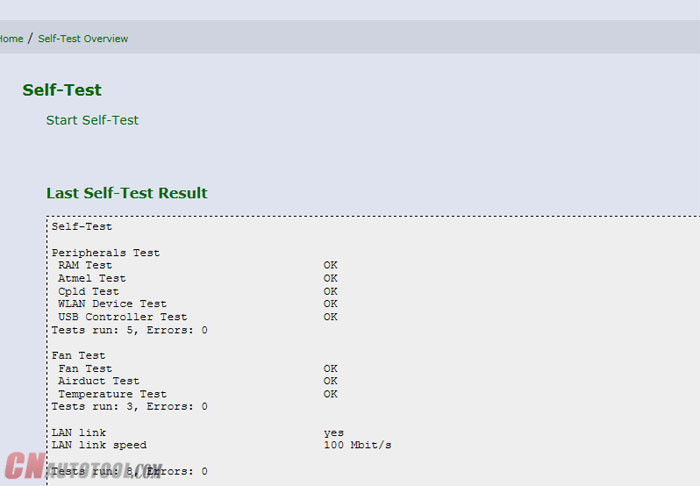
make a self-test, than you can got the test result , the WIFI function must be OK
15-1
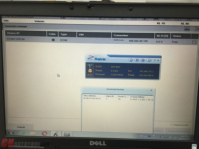
STEP2:Go to 169.254.92.38/58000 make the WIFI setting, ( the bmwicomshop.com bmw ICOM a2 WIFI version no need setting)
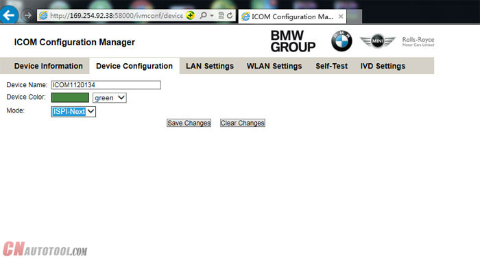
a . Set the mode to ISPI-NEXT
15-2
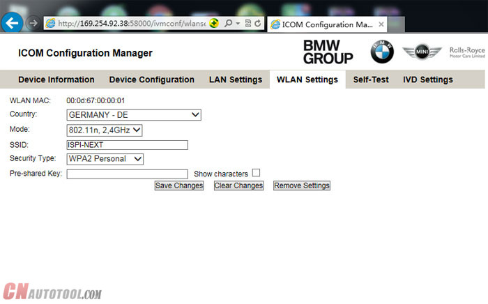
b . SET WLAN , SSID name ISPI-NEXT PASS:12345678 save
15-3
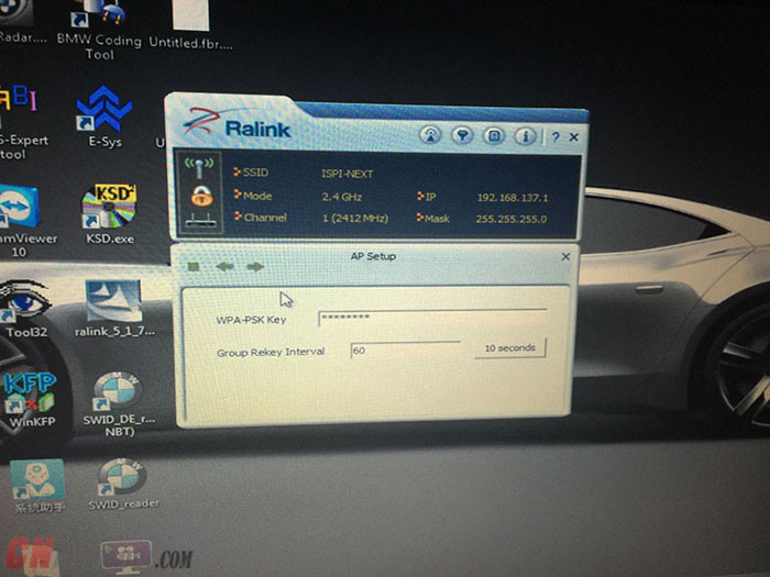
After the setting on ICOM is done , let’s make computer setting, suggest buy the a USB WIFI card , then set it to AP mode
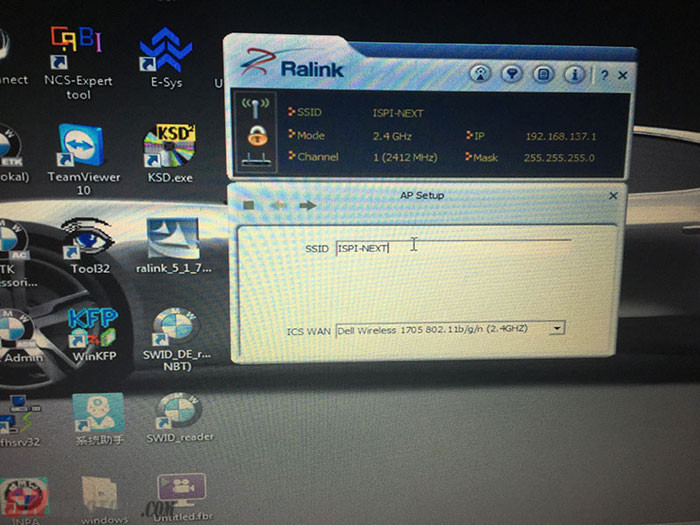
Then set same SSID name as ICOM Next; ISPI-NEXT
And choose WSP2 method , enter same password :12345678
15-4
15-5
Then OK, unplug ICOM LAN cable, restart ICOM waiting it connect to laptop WIFI!
15-6
Then start ISTA/D make diagnostic. Enjoy!

HOW TO DO PROGRAMMING WITH ISTA+

Until now, different systems for BMW diagnostic tool vehicle diagnosis (ISTA) and programming (ISTA/P) have been used. This means it was necessary to change systems several times when repairing a vehicle using software.
ISTA+ has been expanded so that all the required programming functions for the series F, G and I are integrated.
E-series vehicles still have to be programmed using ISTA/P!
The functions relevant for programming can be accessed via the following menus:
13-1
Vehicle treatment
● Software update
● Comfort – as per the suggested measures plan
● Advanced – with broadened scope
● Additional software (range of functions is not active yet)
● Control unit replacement
● Before exchange (preparation) – control unit read-out for the exchange
● After exchange (subsequent evaluation) – control unit configuration after exchange
● Vehicle modification
● Retrofit
● Conversion o Conversion (only coding)
● Back fitting
● Immediate measures
13-2

HOW TO DO DIAGNOSTICS USING ISTA+

How to start the ISTA workshop system:
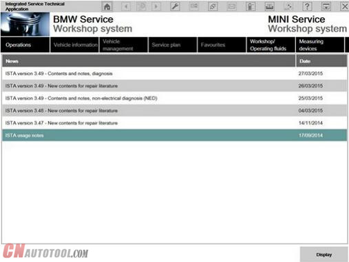
Double click the BMW diagnostic software ISTA+  icon in the Windows desktop created during the installation process above. After ISTA is started, the start screen appears. A list of news is displayed. You can set the display period in the Administration.
12-1
Once you have read the “Note on using ISTA”, close the dialog using the button “Next”. You can open a process from the start screen: Select the “Operations” menu.
SELECTING A VEHICLE WITHOUT CABLE CONNECTED TO CAR
Method 1:
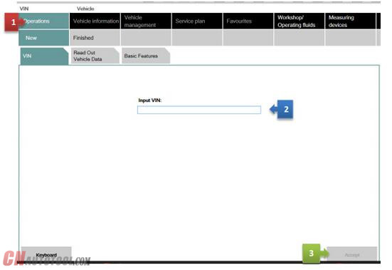
You can enter your short VIN (Last 7 of the VIN) and be able to pull relevant procedures or troubleshooting instructions without actually connecting to the car. To access this feature, launch ISTA+ and click on Operations tab (1). Then enter the short VIN into the VIN box (2). Then click on Accept (3). The Accept button will become active only when a VIN number is entered. You can explore features specific to your car from here.
12-2
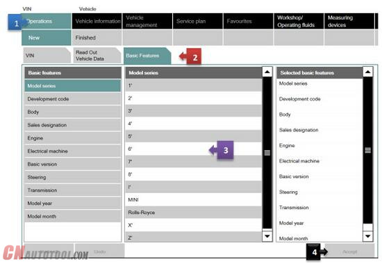
Method 2:
Follow the steps as in the picture below:
12-3
SELECTING A VEHICLE VIA “READ OUT VEHICLE DATA” WITH CABLE CONNECTED TO CAR
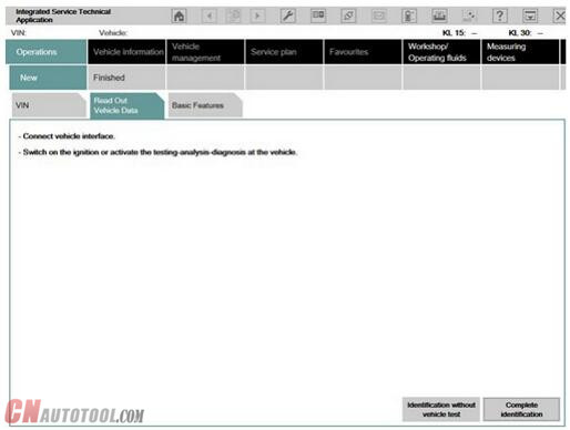
After you select the “Operations” menu from the start screen, the workshop system changes to the “Vehicle identification number” tab under the “New” menu item.
We will assume that you have connected the right interface to the car at this time (Refer to interfaces section). Our example will use BMW ICOM A2+B+C.
This is how to identify a vehicle by reading out the vehicle data, while automatically creating a process:
1 Click the “Operations” main menu item in the navigation area.
2 Select the “Read out vehicle data” tab and follow the instructions provided.
3 Click the “Identification without vehicle test” or “Complete identification”button
12-4
The connection to the vehicle is now established. The workshop system performs an identification of the vehicle. It also reads the vehicle identification number and further data from the vehicle. The progress of the identification operation is displayed on a progress bar.
12-5
Start vehicle test
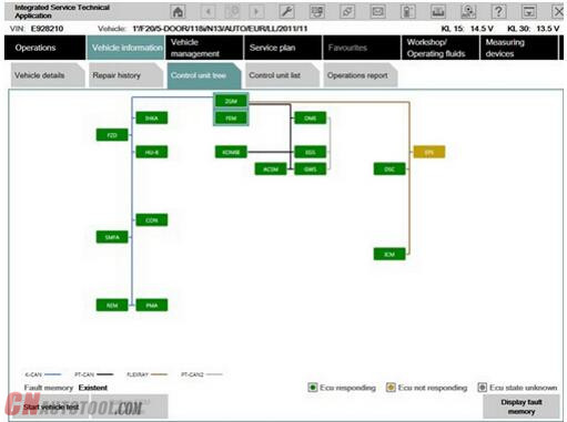
If vehicle identification was called up via “Read out vehicle data” and “Complete identification”, the vehicle test starts automatically following vehicle identification, followed by the vehicle operation and service data transfer and analysis. The control unit tree is displayed during the vehicle test
12-6
Here you can observe the ongoing determination of the control units that are fitted. If no control unit tree is available, the “Control unit list” mask is displayed automatically.
The control unit tree contains all the control units identified in the vehicle and displays their allocation to the relevant bus system. The control units are identified in succession and their fault memories are read out. The color then changes to display of the detected state. An explanation of the colors can be found in the lower section of the displayed mask. From this screen, if required you can restart the vehicle test or also call up control unit functions so that you can read out measurements or activate actuating elements.
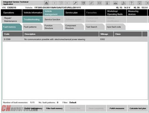
Before you can access a test plan you must first display the fault memory. This is how to view the fault memory:
1 Wait until the vehicle test is completed.
2 Click the “Display fault memory” button.
Show fault memory
After the vehicle test, click the “Display fault memory” button in the “Fault memory” mask. The fault codes that are read out and the associated description are listed here.
12-7
The function “Delete fault memory” can be carried out at the end of the guided troubleshooting. In order to start the guided troubleshooting, first calculate a test plan.
This is how to calculate a test plan:
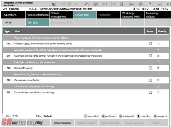
Click the “Calculate test plan” button.
Processing the test plan
The test plan lists the components and functions that might have caused the fault. The documents and test modules corresponding to the components and functions are displayed in the “Type” column, identified with “ABL”. In the “Type” column, documents and test modules are identified with an abbreviation.
Procedures localize a fault and give advice on rectifying it. This is how you start a procedure:
1 Select the required procedure from the test plan.
2 Click the “Display” button.
12-8
The priority in the test plan does not necessarily specify the call-up of the processes. The priority is to be regarded as a recommendation for processing.
A test module is primarily designed to identify the cause of a fault. Furthermore, service functions can be performed via procedures. Information can be displayed within a test module, as well as measured values read out or entered. Furthermore, queries can be made available in procedures via selection screens.
After a test module has been carried out, additional information is added to the test plan if this is necessary for further troubleshooting or fault elimination.
12-9
After the test plan has been completed, you should carry out the “Delete fault memory” function.
This article is posted by www.cnautotool.com. if you have questiones, please contact us sale@cnautotool.com
HOW TO USE BMW RHEINGOLD ISTA WITH BMW ENT CABLE

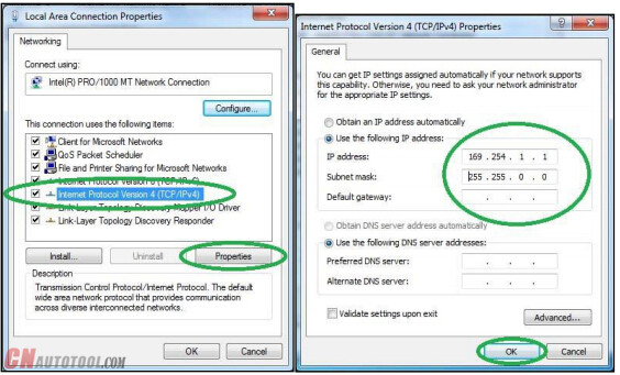
1. Open used for connection network adapter properties, then “Internet Protocol Version 4 (TCP/IPv4)” properties, then enter 169.254.1.1 for “IP address” and 255.255.0.0 for “Subnetmask”.
11-1
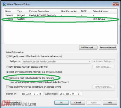
2. If VMware is installed, open Virtual Network Editor and disconnect from the host any adapters with Subnet Address 169.254.0.0.
11-2
3. Connect car with ENET cable to PC, turn ignition on.
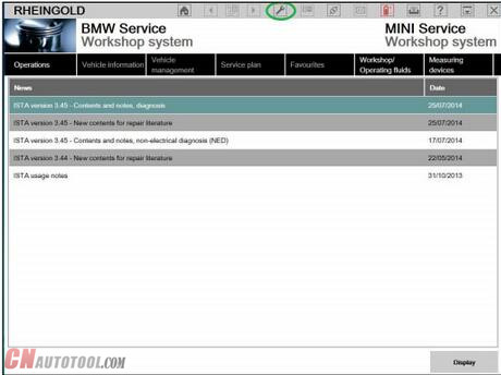
4. Now run BMW diagnostic tool BMW Rheingold ISTA using shortcut in start menu and wait until it boots, then press settings button.
11-3
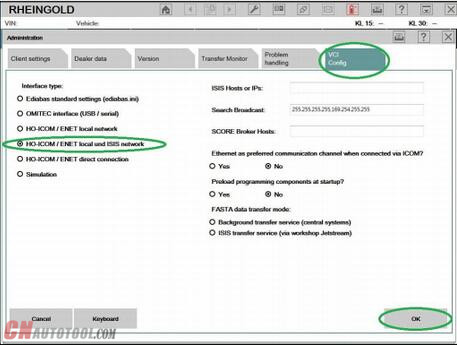
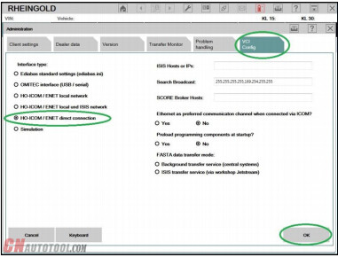
5. Select “VCI Config” tab and “HO-ICOM/ENET local and ISIS network”, then “OK”.
11-4
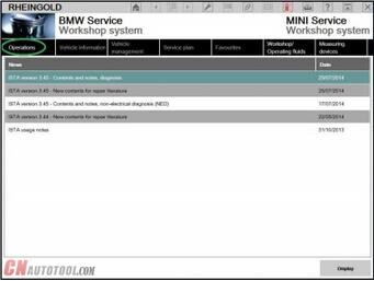
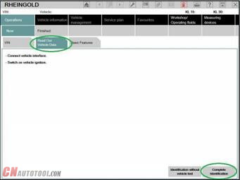
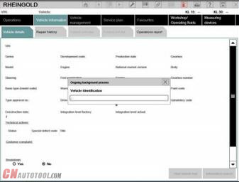
6. Go “Operations”, then “Read Out Vehicle Data” and “Complete Identification”.
11-5
11-6
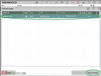
7. Select your ENET connection from the list and press “Set up connection”button.
11-7
11-8
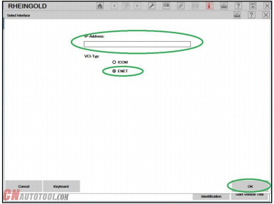
8. Alternatively you could select “HO-ICOM/ENET direct connection” in “VCI Config” tab and “ENET” mode with empty “IP-Address” field during connection setup.
11-9
11-10

What is used for BMW G30 ECU flash

Purpose: Need to flash a BWM G series G30
Puzzle: Is the ICOM Next mandatory or is the up to date ICOM 1st generation ICOM from 2012 ok?
Can I flash NBT EVO with old ICOM?
Advice & Options:
1.
ENET cable would probably be better for you.
2.
I flashed NBT EVOs with old ICOM without problems.
3.
Flashed all Cars with ICOM Next and Online Aos with DHCP over Router. Since that i have Never any Problems with NBT or other. Flash E/F/G with this Setup.
Note that Online Aos is the online version of the BMW software for Diagnostic, Programming any many other things.
4.
To answer your question
1st : you doesn’t need iCOM NEXT ON CnAutotool to flash the G series…but It actually Lot better & save up your times because iCOM NEXT has build in Gigabit connection.
2nd : old iCOM working find. It just take a lot longer.
5.
Icom best any type , router I noticed w my setup I use desktop w 2 lan port and on a few f cars it actually faster then oem it programs up to 8 module same time w gigabit switch , and handle data lots faster than etnet cable and for certain modules the router is a must will crash hu high in kombi in a few others
6.
Any icom will work , but to be safe with f,g,i series vehicles , use a dedicated router as kafas huh and a few other modules will crash if you do not use a router it handles the switches for Ethernet as those modules use more than 1 path way , in short it uses all 4 two pair wires and without router not good , this has worked for me for some time now good luck. note my router does not connect to wan
Conclusion:
ICOM Next is the best option for G series, working better and faster than old BMW ICOM cables. It handles multiprogramming and coding quite nicely. Gets the job done much faster if flashing the complete vehicle. Also, another benefit to Next will be compatibility for future cars.

How to Use BMW Rheingold ISTA to Do Programming and Coding

BMW Rheingold ISTA is a software program used by BMW technicians for programming and coding various modules in BMW vehicles. It is an essent...